- 您现在的位置:买卖IC网 > Sheet目录323 > DV164131 (Microchip Technology)KIT STARTER PICKIT 3
�� �
�
�PICkit?� 3� User’s� Guide�
�Additionally,� MCLR� is� also� used� as� either� a� high� voltage� programming� signal� or� as� an�
�attention� indicator� to� the� device.�
�In� order� to� have� trouble� free� in-circuit� debugging,� careful� planning� must� be� done� by� the�
�designer� to� avoid� any� problems� during� the� application� development� or� production�
�phase� of� the� product.�
�RECOMMENDED� CONFIGURATION�
�The� signals� PGC� and� PGD� are� active� bidirectional� signals� driven� by� the� PICkit� 3� and�
�target� emulation� device.� If� these� signals� can� be� kept� free� from� any� other� passive� circuits�
�or� active� logic� in� the� application,� it� will� ensure� trouble� free� debugging� and� programming�
�sessions.� Also,� cable� length� and/or� type� may� be� negligible� with� this� configuration.�
�Additionally,� the� MCLR� signal� is� used� by� PICkit� 3� to� provide� the� voltage� used� for� pro-�
�gramming� some� devices� or� to� signal� attention.� In� instances� where� the� application� has�
�a� large� capacitor,� it� will� cause� the� signal� rise� and� fall� time� to� degrade.� This� will� hinder�
�the� ability� of� PICkit� 3� and� the� device� to� communicate� effectively.� It� is� recommended� to�
�keep� the� signal� pulled� up� to� V� DD� with� a� 10K� resistor,� and� to� utilize� the� power-on� timer�
�features� of� the� device� to� ensure� a� proper� power-up� sequence.�
�ALTERNATE� CONFIGURATION�
�In� some� cases,� especially� with� low� pin� count� devices,� the� pins� must� be� utilized� by� the�
�application.�
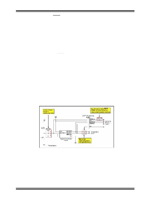
�If� this� is� the� case,� as� a� minimum,� a� resistive� isolation� is� required� between� the� device�
�and� the� application� active� node.� This� will� ensure� that� both� the� application� circuit� and�
�PICkit� 3� are� able� to� drive� the� PGC� or� PGD� node� to� ground� and� to� the� proper� V� DD� levels.�
�Figure� B-1� depicts� this� configuration.�
�FIGURE� B-1:�
�TYPICAL� ICSP?� APPLICATION� CIRCUIT�
�The� resistive� isolation� value� will� differ� depending� on� the� application� and� how� it� is� being�
�used.� Values� ranging� from� 1K� to� 10K� are� suggested.� In� any� case,� ensure� the� levels� on�
�PGD� and� PGC� can� be� driven� to� their� appropriate� logic� voltage� levels.�
�COMMUNICATION� CHANNEL�
�Some� devices� have� the� flexibility� to� use� one� of� several� communication� channels� or� pins�
�for� programming� and� debugging.� These� channels� are� generally� referred� to� in� data�
�sheets� as� PGCx/PGDx,� where� x� is� channel� number� identifier.� These� channels� are� often�
�multiplexed� with� some� peripherals� (I� 2� C?,� SPI,� A/D).� If� your� application� uses� those�
�DS51795A-page� 68�
�?� 2009� Microchip� Technology� Inc.�
�发布紧急采购,3分钟左右您将得到回复。
相关PDF资料
DV164132
KIT EVAL F1 FOR PIC12F1/PIC16F1
DV243003
KIT STARTER FOR SRL MEM PRODUCTS
DVA1001
ADAPTER FOR PIC16F716 18DIP
DVA1004
DEVICE ADAPTER 8/14/20DIP
E3R-D12GP-P
RELAY RCVR PLUG-IN DIMMER
E3R-R12-3HOTP
RCVR 3WIRE RELAY 120V
E3R-R12GP
RCVR PLUG-IN RELAY
E3T-MICFP-40
CONVERTER 4-CH SLT SENSOR
相关代理商/技术参数
DV164131
制造商:Microchip Technology Inc 功能描述:PICKIT 3 DEBUG EXPRESS
DV164131-XLP
制造商:Microchip Technology Inc 功能描述:KIT DEV PICKIT 3-XLP/NANOWAT
DV164132
功能描述:开发板和工具包 - PIC / DSPIC F1 Evaluation Kit RoHS:否 制造商:Microchip Technology 产品:Starter Kits 工具用于评估:chipKIT 核心:Uno32 接口类型: 工作电源电压:
DV164132
制造商:Microchip Technology Inc 功能描述:PIC12F1xxx/PIC16F1xxx F1 Evaluation Kit
DV164133
功能描述:电源管理IC开发工具 Energy Harvesting Development Tool
RoHS:否 制造商:Maxim Integrated 产品:Evaluation Kits 类型:Battery Management 工具用于评估:MAX17710GB 输入电压: 输出电压:1.8 V
DV164136
功能描述:开发板和工具包 - PIC / DSPIC PIC18F DEV Kit (with PICkit 3) RoHS:否 制造商:Microchip Technology 产品:Starter Kits 工具用于评估:chipKIT 核心:Uno32 接口类型: 工作电源电压:
DV164139
功能描述:开发板和工具包 - PIC / DSPIC Lo PIn Count USB Dev Kit (w/PICkit 3) RoHS:否 制造商:Microchip Technology 产品:Starter Kits 工具用于评估:chipKIT 核心:Uno32 接口类型: 工作电源电压:
DV17K3225T
制造商:SEI Stackpole Electronics Inc 功能描述:- Tape and Reel 制造商:SEI Stackpole Electronics Inc 功能描述:Var MOV 17VAC/22VDC 100A 27V 3225 SMD T/R